Trong kỷ nguyên số hóa ngành xây dựng và kết cấu thép, việc tối ưu hóa quy trình mô hình hóa thông tin công trình (BIM) không còn là một lựa chọn mà đã trở thành yêu cầu bắt buộc để nâng cao năng lực cạnh tranh. PEB Section Creator ra đời như một giải pháp đột phá, giải quyết triệt để bài toán phức tạp và tốn thời gian nhất trong thiết kế nhà thép tiền chế: Quản lý thuộc tính và tự động hóa dựng hình các cấu kiện biến đổi tiết diện (tapered members) trực tiếp trên nền tảng Tekla Structures.
Tại sao cần PEB Section Creator?
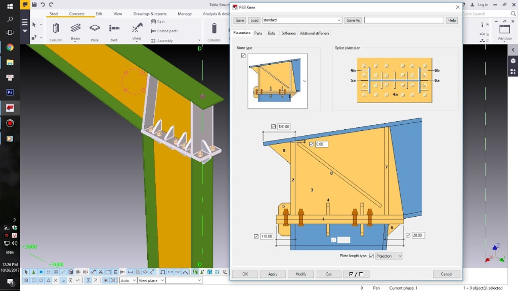
Thiết kế nhà thép tiền chế (PEB) đòi hỏi các cấu kiện dầm và cột có tiết diện thay đổi liên tục (tapered sections) để phân bổ ứng suất tối ưu, giảm thiểu khối lượng thép và tiết kiệm chi phí vật liệu tối đa. Việc tạo lập và quản lý thủ công hàng trăm file thuộc tính cấu kiện biến đổi này trong thư mục attributes của Tekla Structures là một cơn ác mộng thực sự: tốn hàng giờ bấm chuột, dễ nhầm lẫn thông số hình học và vô cùng khó khăn khi dự án có thay đổi thiết kế.
Các Tính Năng Vượt Trội
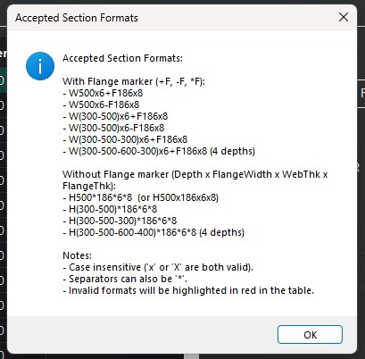
- Định nghĩa tiết diện đa điểm linh hoạt: Hỗ trợ nhập và tự động phân tích các định dạng tiết diện từ đơn giản đến phức tạp: từ tiết diện không đổi đến biến đổi 2 điểm, 3 điểm, thậm chí 4 điểm chiều sâu web (ví dụ:
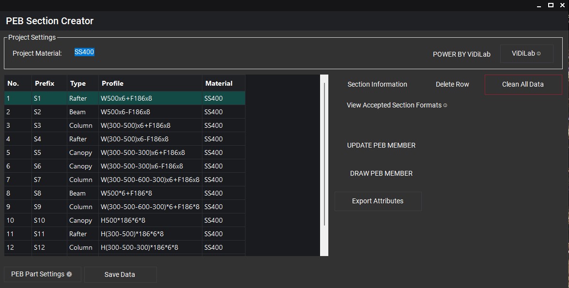
W(300-500-600-300)x6+F186x8). - Giao diện thông minh và tối giản: Bố cục được sắp xếp lại vô cùng tinh gọn, loại bỏ các cài đặt prefix thừa thãi giúp kỹ sư chỉ cần tập trung vào vật liệu dự án (Project Material). Định dạng tiết diện sai cú pháp sẽ lập tức bị bôi đỏ cảnh báo trực quan trên bảng dữ liệu Grid.
- Thuật toán phân loại Class thông minh (4 Chế độ): Thay vì cấu hình thủ công phức tạp, hộp thoại Part Settings mới tích hợp bộ chọn Class By linh hoạt:
- By Thickness: Tự động gán Class theo chiều dày bản cánh và bản bụng cấu kiện (làm tròn mm), hỗ trợ đắc lực cho quản lý sản xuất theo chiều dày phôi.
- By Section: Tự động lọc tất cả các loại tiết diện khác nhau trong dự án, sắp xếp theo thứ tự bảng chữ cái và đánh số Class duy nhất từ
1đến99. - By Prefix: Tự động trích xuất các chữ số ở đuôi của cột Prefix (ví dụ: tiền tố
S12tương ứng với Class12) để đồng bộ với bản vẽ xuất xưởng. - By User: Cho phép người dùng nhập trực tiếp một số Class mặc định duy nhất áp dụng cho tất cả cấu kiện.
- Dựng mô hình 3D trực tiếp (Draw PEB Member): Dựng trực tiếp cấu kiện 3D vào mô hình Tekla Structures bằng cách chọn 2 điểm. Ứng dụng xử lý cấu hình động trực tiếp trong bộ nhớ, không để lại bất kỳ file XML thuộc tính rác nào trong thư mục dự án.
- Cập nhật hàng loạt (Update PEB Member): Chọn bất kỳ số lượng cấu kiện PEB nào trên mô hình Tekla và nhấn nút để đồng bộ tức thời các thông số về tiết diện, vật liệu và quy tắc màu sắc (Class).
Hướng Dẫn Sử Dụng Chi Tiết
Bước 1: Nhập và kiểm tra dữ liệu tiết diện
Người dùng có thể sao chép nhanh danh sách tiết diện từ Excel và dán trực tiếp vào bảng Grid của PEB Section Creator. Sử dụng nút Accepted Formats để xem các định dạng ký hiệu được hỗ trợ. Định dạng hợp lệ sẽ được tự động tách các trường kích thước (bản bụng Web, bản cánh Flange, chiều dày WebThk, FlgThk, các điểm chiều sâu d1, d2, d3, d4) để tính toán tự động.
Bước 2: Cấu hình quy tắc gắn thuộc tính (Part Settings)
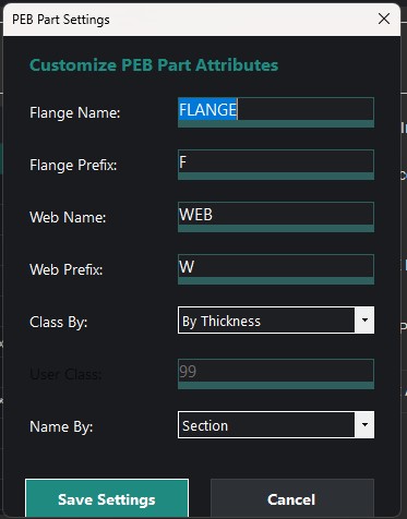
Click nút PEB Part Settings ở góc dưới bên phải giao diện chính. Tại đây, bạn thiết lập:
- Tên gọi (Name) và tiền tố bản vẽ (Prefix) riêng biệt cho bản cánh (Flange) và bản bụng (Web).
- Bộ quy tắc gán màu sắc/phân lớp cấu kiện tại ComboBox Class By. Nếu chọn chế độ By User, ô nhập User Class sẽ được kích hoạt để bạn điền thông số. Nhấn Save Settings để lưu lại cấu hình và áp dụng đồng loạt cho toàn bảng.
Bước 3: Dựng mô hình 3D trực tiếp trong Tekla Structures
1. Chọn dòng tiết diện mong muốn dựng hình trên bảng Grid.
2. Nhấn nút DRAW PEB MEMBER. Cửa sổ ứng dụng sẽ tạm thời ẩn đi để tối ưu không gian thao tác.
3. Trên mô hình Tekla Structures, thực hiện click chọn 2 điểm: Điểm đầu (Start Point) và Điểm cuối (End Point).
4. Cấu kiện PEB Member sẽ được dựng chính xác tức thì. Ứng dụng sẽ tự động hiển thị trở lại để bạn tiếp tục làm việc.
Bước 4: Cập nhật cấu kiện hoặc Xuất thuộc tính hàng loạt
Để cập nhật tiết diện mới cho các cấu kiện đã dựng sẵn, hãy chọn cấu kiện đó trên mô hình Tekla, chọn dòng tiết diện tương ứng trong bảng Grid của tool, sau đó nhấn UPDATE PEB MEMBER. Ngoài ra, bạn có thể chọn nhiều dòng tiết diện trong Grid và nhấn Export để lưu trữ các file cấu hình XML chuẩn hóa vào mô hình phục vụ cho các công tác thiết kế liên kết sau này.
In the era of construction and steel structure digitalization, optimizing Building Information Modeling (BIM) workflows is no longer optional—it is a critical requirement to improve competitiveness. PEB Section Creator stands out as a breakthrough solution that completely automates and simplifies the most complex and time-consuming tasks in Pre-Engineered Building (PEB) design: managing attributes and automatic 3D modeling of tapered members directly inside Tekla Structures.
Why Choose PEB Section Creator?
PEB design requires column and rafter members with continuously varying (tapered) sections to optimize load distribution, minimize steel weight, and maximize cost efficiency. Manually creating and managing hundreds of XML attribute files in the Tekla Structures attributes folder is a real workflow bottleneck: requiring endless repetitive mouse clicks, prone to parameter input errors, and extremely difficult to modify when design revisions occur.
Key Features
- Flexible Multi-Point Sections: Supports and automatically parses simple to highly complex section formats: from constant profiles to 2-point, 3-point, or even 4-point tapered web depths (e.g.,
W(300-500-600-300)x6+F186x8). - Clean and Streamlined Interface: The layout is rearranged to be highly compact, removing redundant prefix controls and allowing engineers to focus solely on project material settings. Invalid profile formats are instantly highlighted in red on the DataGrid for rapid error correction.
- Smart Class Assignment (4 Modes): In the updated Part Settings dialog, a highly versatile Class By ComboBox lets you define class assignment rules:
- By Thickness: Automatically sets classes based on flange and web plate thicknesses (rounded to nearest mm)—ideal for manufacturing plate nesting and stock management.
- By Section: Automatically aggregates all unique profiles in your project, sorts them alphabetically, and assigns sequential class IDs from
1to99. - By Prefix: Dynamically extracts trailing digits in the Prefix column (e.g., prefix
S12yields Class12) to align with standard drawing output. - By User: Allows you to enter a single, custom default Class number for all components.
- Direct 3D Modeling (Draw PEB Member): Insert 3D components directly into Tekla by picking 2 points. The application handles all temporary configurations in memory, leaving zero redundant XML attribute files in your directory.
- Batch Member Updates (Update PEB Member): Select any number of PEB components directly inside your active Tekla model and click to instantly synchronize their profiles, materials, and class rules.
Step-by-Step User Manual
Step 1: Input and Validate Section Data
You can quickly copy lists of profiles from Excel sheets and paste them directly into the DataGrid. Click Accepted Formats to review supported notation formats. Valid rows are automatically parsed into individual component metrics (Web, Flange, WebThk, FlgThk, d1, d2, d3, d4 depths) for downstream calculations.
Step 2: Configure Parts Attributes (Part Settings)
Click the PEB Part Settings button at the bottom right. Here, you can configure:
- The Name and drawing Prefix for both Flanges and Webs separately.
- Your classification rules via the Class By ComboBox. If By User is selected, the custom User Class input box is enabled. Click Save Settings to commit the configuration and apply it across all rows instantly.
Step 3: Model 3D Components in Tekla Structures
1. Select your target profile row in the DataGrid.
2. Click the DRAW PEB MEMBER button. The app window will temporarily minimize to maximize your screen space.
3. Inside the Tekla Structures 3D model, click to pick two coordinates: the Start Point and the End Point.
4. The 3D PEB Member component is generated instantly. The app window automatically restores itself so you can continue your design.
Step 4: Update or Batch Export Attributes
To modify existing structures in your model, select the components inside Tekla, choose your new profile row in the grid, and click UPDATE PEB MEMBER. You can also select multiple grid rows and click Export to automatically output optimized XML files to your model's attributes directory for subsequent detailing work.